Lots of graphics and video effects can be described by a coordinate transformation: There is a rule for calculating destination coordinates from the source coordinates. The rule completely describes the type of transformation.
The most prominent family of transformations are the affine transforms, where the transform rule can be described by a vector matrix multiplication:
(xdst, ydst) = (A) (xsrc, ysrc)
With this one can implement e.g. scaling and rotation. If the vectors and matrix are given in homogeneous coordinates, one can also shift the image by a vector. Other transforms can be Lens distortion, perspective distortion, wave effects and much more.
Now the question: how can such a transform be implemented for digital images? The algorithm is straightforward:
- Find the inverse transform. For affine transforms, it will simply be the inverse matrix. For other transforms it might not be that easy. The inverse transform will give you the source coordinates as a function of the destination coordinates
- For each destination pixel, find the coordinates in the source image
- If the source coordinates are fractional (they usually will be), interpolate the destination pixel from the surrounding source pixels
Since the interpolation is always the same I decided to implement this in a generic way in gavl (
gavl_image_transform_t). With this we can implement lots of different transforms by just defining the inverse coordinate transform as a C-function and passing it to the interpolation engine. While the algorithm is simple in theory the implementation has to take care for some nasty details:1. Y'CbCr formats with subsampled chroma planes
In the video area, these are the rule rather than the exception. Many filters don't support them and use an RGB format instead (causing some conversion overhead). They can, however, be handled easily if you set up separate interpolation engines for each plane. For the subsampled planes, you do the following:
- Transform the coordinates of the chroma location to image coordinates (i.e. multiply by the subsampling factors and shift according to the chroma placement)
- Call the function to get the source coordinates the usual way
- Transform the source coordinates back to the coordinates of the chroma plane
This is e.g. the case where an image is downscaled. Gavl handles these by not touching the destination pixel at all. Then you can fill the destination frame with a color before the transformation and this color will be the background color later on.
3. Destination pixel is inside the source image, but surrounding pixels (needed for interpolation) are not
Here, one can discuss a lot what should be done. For gavl, I decided to assume, that the "missing pixels" have the same color as the closest border pixel. The reason is, that instead of handling all possible cases inside the conversion loop for each pixel (which will slow things down due to the additional branches), one can simply shift the source indices and modify the interpolation coefficients once during initialization. The following figure illustrates, how this is done:
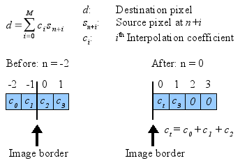 The start index n and the interpolation coefficients are saved in the interpolation table. After shifting the table, the interpolation routine works without branches (and without crashes). Due to the way the interpolation coefficients are modified we assume that the missing pixels at -2 and -1 are the same color as the border pixel at 0. Of course this is done for x and y directions and also for the case that indices are larger than the maximum one.
Usage
The image transformation is very easy to use, just get the gavl from CVS and read the API documentation. There is also a gmerlin filter in CVS (
fv_transform) which can be used as reference. Some questions might however arise when using this:1. How exactly are coordinates defined?
Gavl scaling and transformation routines work with subpixel presision internally. This is necessary, if one wants to handle chroma placement correctly. To make everything correct one should think a bit how coordinates are exactly defined. This is an example for a 3x3 image:
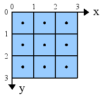 The sample values for each pixel are taken from the pixel center. This means, the top-left pixel has a color value corresponding to the location (0.5, 0.5). For chroma planes, the exact sample locations are considered as described here.
2. Handling of nonsquare pixels
These must be handled by the coordinate transform routine provided by you. Basically, you have a "sample aspect ratio" (
sar = pixel_width / pixel_height). In your transformation function, you do something like:
x_dst *= sar; /* Distorted -> undistorted */

/* Calculate source coordinate assuming undistorted image */

x_src /= sar; /* Undistorted -> distorted */
3. Image scaling
One is tempted to think, that this all-in-one solution can be used for scaling as well. It is, of course true, but it's a stupid thing to do. Scaling can be highly optimized in many ways. The
gavl_video_scaler_t does this. It's thus many times faster than the generic transform.4. Downsampling issues
The image transform makes no assumptions about the type of the transform. Especially not if the transform corresponds to downsampling or not. And this is where some issues arise. While for upsampling it's sufficient to just interpolate the destination pixels from the source pixels, for downsampling the image must be low-pass filtered (i.e. blurred) first. This is because otherwise the sampling theorem is violated and aliasing occurs. A very scary example for this is discussed here. One more reason to use the
gavl_video_scaler_t wherever possible because it supports antialiasing filters for downscaling. The good news is that usual video material is already a bit blurry and aliasing artifacts are hardly visible.Examples
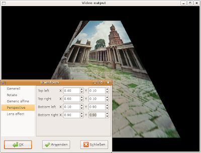
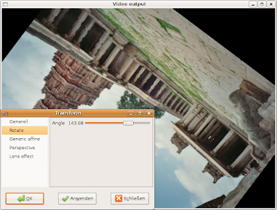
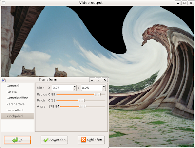
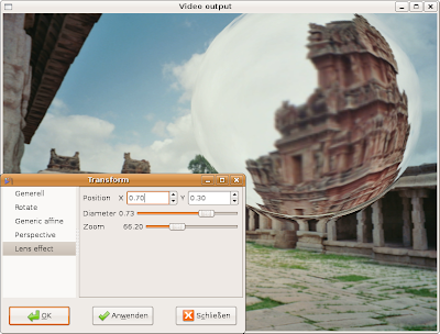
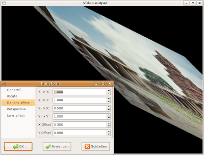
After this much theory, finally some examples. These images were made with the gmerlin transform filter (the original photo was taken in the South Indian ruin city of Hampi).


No comments:
Post a Comment